
Last Updated: 2023/11/20
What is SLS?
SLS (Selective Laser Sintering) 3D printing is a technology that uses a high-power laser to fuse powdered material, bonding it together to create solid parts. Unlike traditional FDM (Fused Deposition Modeling) 3D printing, which extrudes melted plastic through a nozzle, SLS doesn't require support structures as the unsintered powder supports the part during printing. This allows for the production of more complex geometry and the utilization of the entire build volume. However, traditional SLS systems are cost prohibitive and messy, making it inaccessible to most people.
Our printing system simplifies this process, offering SLS technology in a compact and user-friendly package. The system's minimal need for support equipment offers unparalleled flexibility, while our custom software with interactive nesting and advanced laser control ensures that the machine’s capabilities are fully utilized. An integrated material handling system reduces downtime while its compact footprint and low power draw facilitates a distributed manufacturing setup.

SLS Workflow
Slice
The first step of starting a new print on our SLS system is to prepare the print file. This is done with MicroSlicer. Import the desired STL models and duplicate as needed. An interactive physics based packing algorithm allows parts to be efficiently packed into the available build volume, achieving maximum throughput.
The model geometries are simplified to create a physics collider, which are then fed into the slicer’s real-time physics simulation engine. The colliders are slightly scaled up so as to provide spacing between parts, ensuring that nearby parts are not fused together. The print volume is set as the bounding box and gravity simulation is applied to all objects, allowing them to be dropped to the lowest practical Z position. Using the mouse, a force can be applied to specific model and to drag it around in the build volume to a desired location. Alternatively, parts can be manually re-arranged using conventional axis bars.
After a satisfactory nesting result is produced, the print file can be generated by clicking the “Slice” button and be transferred to the printer using an SD card or through the local WiFi network.

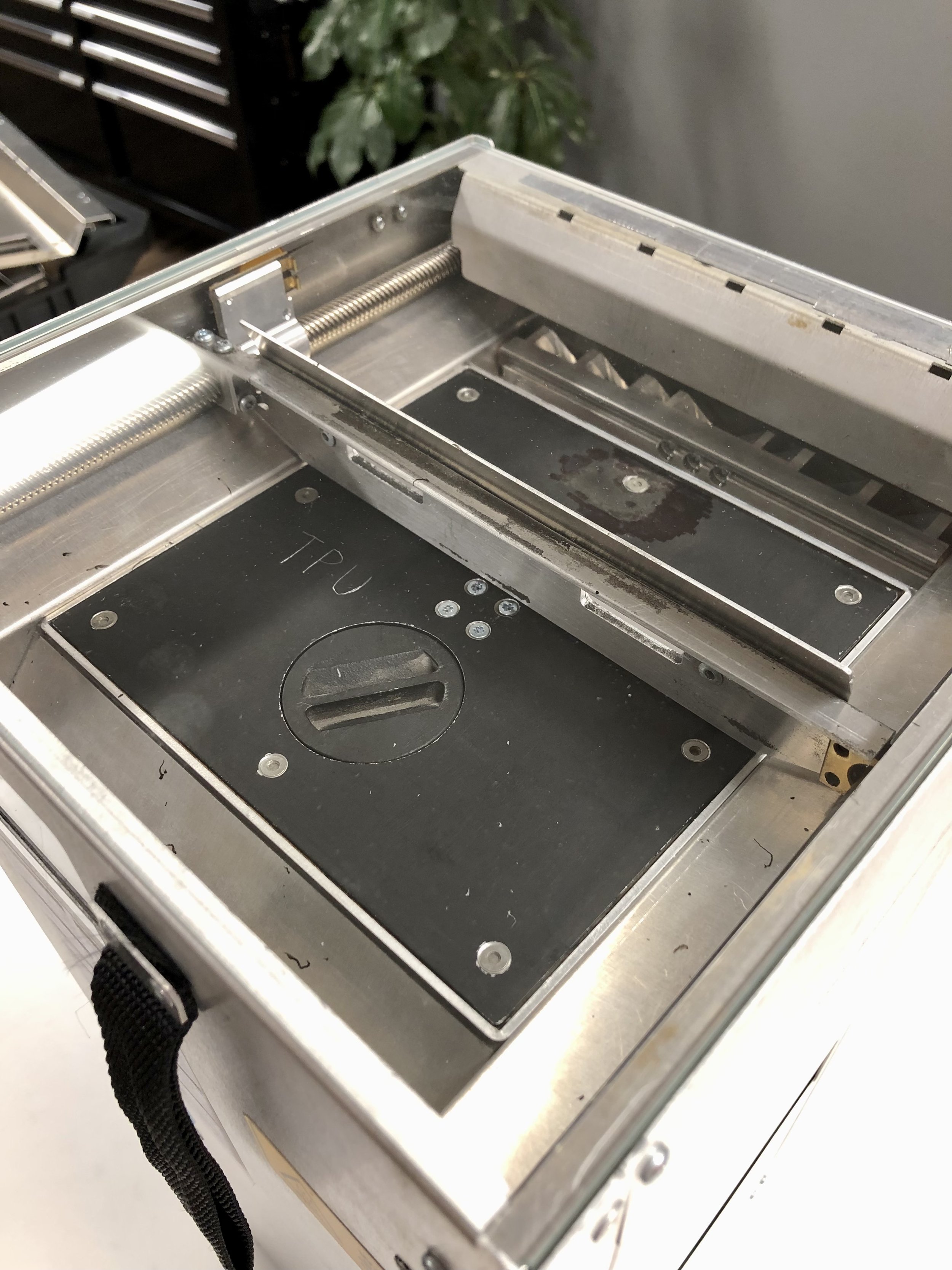
2. Load Material
Each integrated material handling system contains the build area, as well as a material storage compartment. New printing material is loaded and stored under the build plate through an opening in the build plate. During printing, powdered material is transferred to a mixing compartment under the storage compartment through gravity, assisted by vibration. A vertical auger lifts a desired amount of powder from the mixing compartment into a cache compartment adjacent to the top of the build area.
A powder flipper, consisting of a flat surface on the front side and multiple sloped vanes pointing away from the auger on the back side, rotates backwards to pick up the powder from the auger. When the flipper is near the top of the rotation, powder falls through the sloped vanes and are evenly distributed across the width of the cache compartment. After this, the powder flipper is rotated forwards such that the distributed powder is in front of the flipper’s front flat surface. The recoater is then moved over the the cache area and the powder flipper continues to rotate forwards, brining the powder into contact with the recoater and allowing it to be spread across the build area.
Excess powder from the recoating process drops through an overflow chute into the mixing compartment, where it is mixed with new powder from the storage compartment through vibration and ready to be lifted by the auger for use in the next layer.
3. Remove Powder Cake
After the printing process is completed, the printed parts are encased in a powder cake of unfused powder. A transfer tool consisting of a square tube with dimensions slightly larger than the build area and a scoop is used to remove the powder cake. The transfer tube is placed over the build area and the build plate is raised to the top using button button on the build chamber. An internal battery provides power for the lifting motion.
After the powder cake is lifted flush with the top of the build area, the scoop is slid underneath the powder cake and latched with the transfer tube. This can then be removed from the build unit.


4. De-powder
Using the transfer tool, the powder cake is transferred into the manual sifting bin. The bin consists of a top and bottom compartment, separated by a fine mesh sieve in the middle. A pour spout is at the bottom compartment for transferring sifted powder into the build unit. After the powder cake is dropped into the top compartment of the sieve bin, additional new powder is added to the same compartment to replenish the powder for the next print. The lid is closed and the entire bin is shook for around 1 minute. This separates most of the loose powder from the printed parts through the sieve into the bottom compartment. New and old powder are both sifted and mixed together in the bottom compartment during this process and is ready to be loaded back into the print chamber through the pour spout.
The remaining parts in the top compartment can manually brushed off, or be transferred to a bead blasting cabinet or a rotary tumbler to remove the final bits of powder. When using a rotary tumbler, a 50-50 mix of ceramic and stainless steel tumbling media produces good results.
When dropping the powder cake into the bin, removing the lid, or when manually brushing the parts off, dust can be release into the air. This is alleviated using a detachable fume extractor that can be put on at the back of the sifting bin as needed. The fume extractor simply consists of a HEPA filter and fans that draw air, alongside any dust particles into the filter, keeping the surrounding area clean.

